
G. Suwała & Ł. JankowskiA benchmark for identification of structural modifications and inelastic impactsContentsIntroduction
The structure Experimental characteristics of the unmodified structure Identification cases IntroductionOriginally, the benchmark has been described in:G. Suwała, Ł. Jankowski, A benchmark for identification of structural modifications and inelastic impacts: the structure, test data and an example solution, Proc. of the 5th ECCOMAS Thematic Conference on Smart Structures and Materials (SMART'11), 6-8 July 2011, Saarbr³cken, Germany [PDF downloads: paper, slides]. You are invited to download the files and test your identification algorithms. If you do so, please drop me an email, so that I can inform you of updates and corrections (if any). If you share the results of your identification, you will obtain the actual numbers, and if you prefer, your results will be evaluated with respect to other results and listed in this page. The evaluation criteria are described in the slides. The structureThe benchmark uses a commercial construction system of nodes and tubes (MeroForm M12). The catalogue with detailed technical specifications of all elements can be downloaded here or here. The structure is 4 m x 0.5 m x 0.354 m and consists of
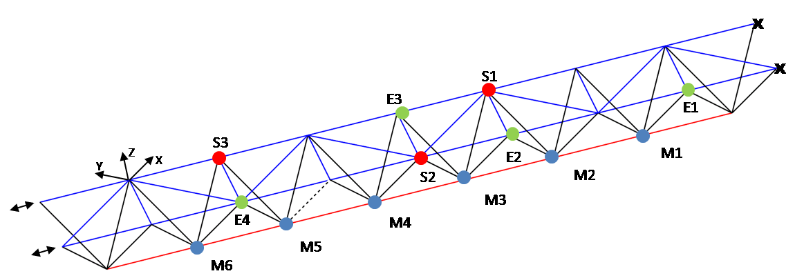 Figure 1. Scheme of
the benchmark structure (click to enlarge)
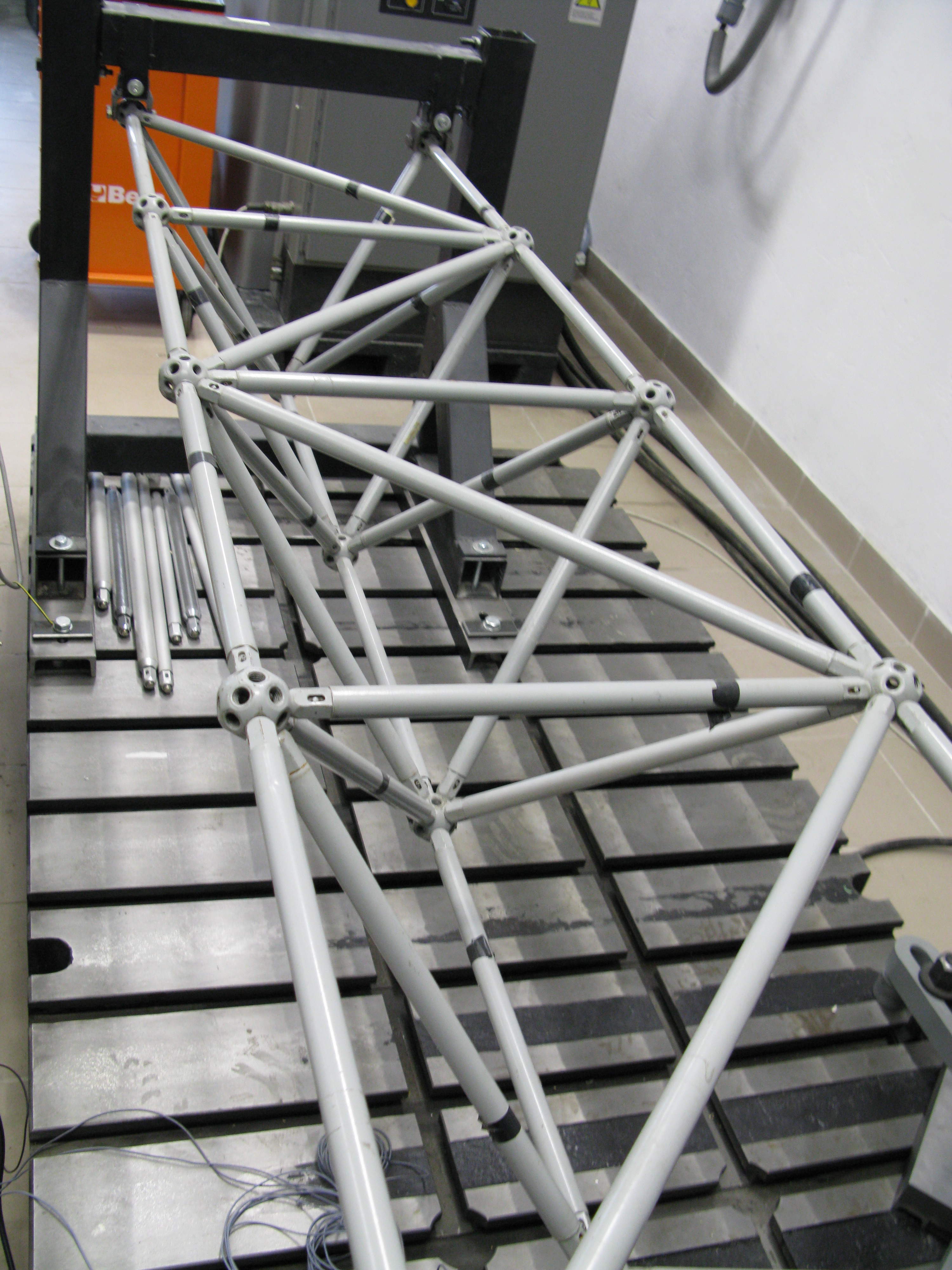 Figure 2. The benchmark structure (click to enlarge) 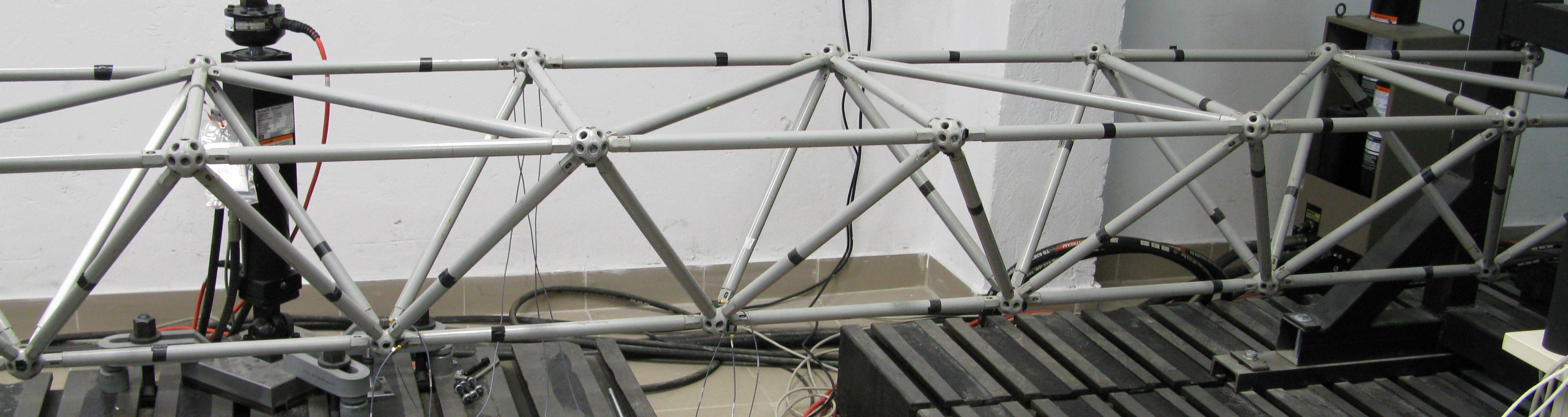 Figure 3. The benchmark structure (click to enlarge) 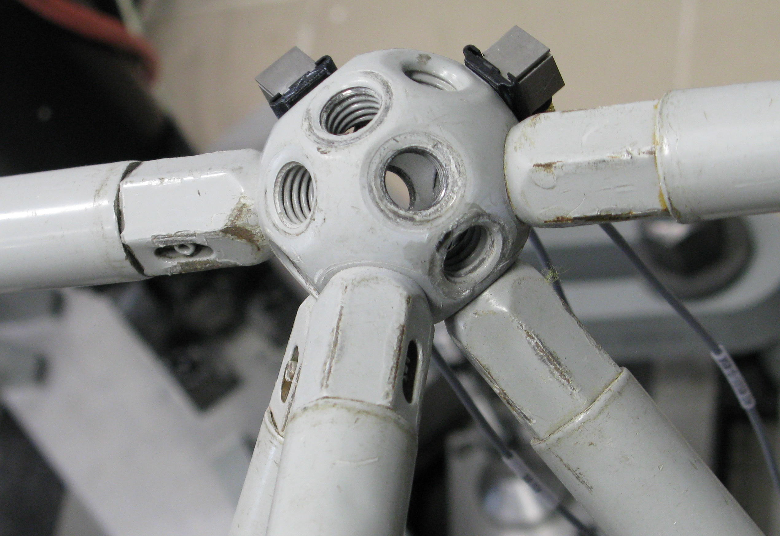 Figure 4. A node of the benchmark structure (click to enlarge) 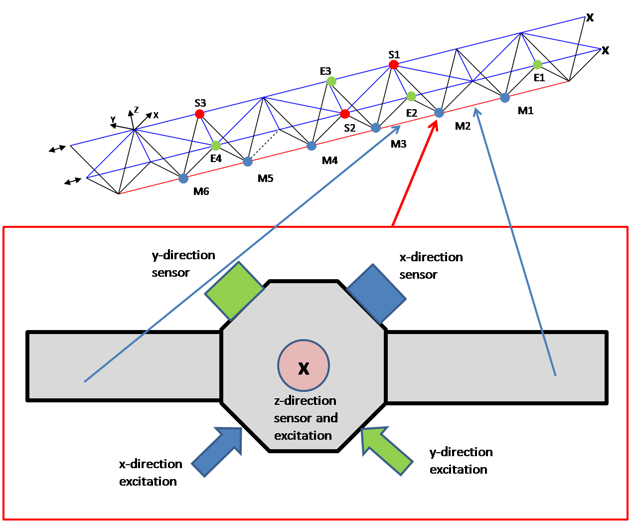 Figure 5. Orientation of axes Experimental characteristics of the unmodified structureThe benchmark is purely experimental. That is, only experimental characteristics of the benchmark structure are provided. There is no "official" parametric numerical model. The experimental characteristics of the original unmodified structure consist of measured quasi impulse responses:
Identification casesThe following identification cases are provided as yet:Single nodal mass modificationAn unknown additional mass has been attached (fixed) to a single node. Experimental characteristics of the modified structure are given by a set of quasi impulse responses:
Modification of two nodal massesTwo unknown additional masses have been attached (fixed) to two selected node. Experimental characteristics of the modified structure are given by a set of quasi impulse responses:
Inelastic impactInelastic impact is simulated by a quasi imulsive excitation (z-direction) of an additional mass attached (fixed) in a selected node. Experimental characteristics of the modified structure are given by a set of the responses to the simulated impact measured in nodes S1 to S3 (z-direction). To increase the accuracy of identification, each impact has been simulated three times. Three subcases are available:
|
IPPT PAN
Adaptronica
EACS 2020