![[E-mail:]](../email.gif) Piotr.Kowalczyk(-at-)ippt.pan.pl )
Piotr.Kowalczyk(-at-)ippt.pan.pl )
Page created and maintained by
Piotr Kowalczyk
(
Piotr.Kowalczyk(-at-)ippt.pan.pl )
Visitors only interested in downloading numerical results, please go here
This is a home page devoted to geometric and mechanical modelling of cancellous bone by analysis of 3D finite element models of equivalent trabecular microstructure. The models are based on assumption of repeatability: identical standard cells with assumed geometry are arranged in rows, columns and layers so as to completely fill 3D space. Geometry of a standard cell is described by Bezier curves and surface patches. Coefficients of the curve/surface nodes are functions of a few scalar shape parameters. At the moment, models described by four shape parameters are considered. Thus, a quadruplet of scalar parameters defines unambiguously a particular instance of trabecular microstructure (in a macroscopic view - a particular type of cancellous bone).
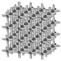
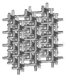
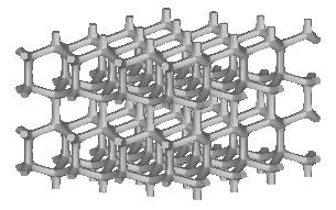
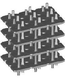
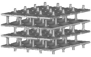
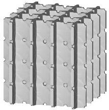
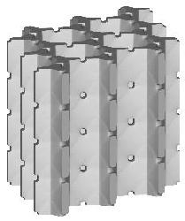
Three types of a standard repeatable microstructural cell are available now. They differ from each other with the shape of a space-filling polyhedron into which the single cell is inscribed. Let us call them: (a) "cubic", (b) "prismatic" (or "wedge"), and (c) "quartz-crystal-shaped" (or "qcs") cells. The unit dimension of the cell is not defined here. For at least some of the measured quantities it is not essential at all, while for the others the results must be scaled by actual trabecular cell size. Remarks about scaling are given on the result description page.
![[cubic cell]](g6pr.jpg)
| ![[prismatic cell]](g5pr.jpg)
| ![[qcs cell]](g4pr.jpg)
|
| "cubic" cell | "prismatic" cell | "qcs" cell |
The first three shape parameters are defined as follows:
tc - average thickness of all plates
th - width of narrowest cross-sections of "horizontal" plates
(i.e. those perpendicular to x3)
tv - width of narrowest cross-sections of "vertical" plates
(i.e. those parallel to x3)
(narrowest cross-sections are those pink shaded in the above figures).
All parameters are dimensionless - they are fractions of unit dimension
of the cell and take values between 0 and 1 (exclusively).
Moreover, th and tv must not be smaller than tc
(in the case they are equal to tc,
the plates become bars with the thickness tc).
The fourth parameter te is defined as a scaling factor
of the entire cell geometry in the x1 direction.
The above pictures show geometry for te=1.
Other values "stretch" or "compress" the cell directionally and introduce
full orthotropy to the models
(for te=1 microstructures are either transversely isotropic or
exhibit cubic symmetry).
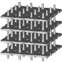
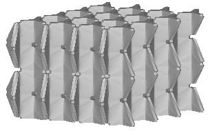
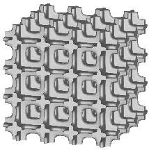
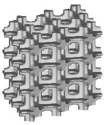
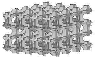
Various combinations of the shape parameter values generate
various typical trabecular microstructure patterns encountered in real bones
(see figures below), as well as many other, possibly never occuring among
trabecular microstructures.
Small values of all parameters correspond to 3D bar structure.
Increasing th drives the microstructure towards an array of parallel
plates with spacer bars.
Increasing otherwise tv generates a honeycomb or square-grid tube.
Increasing both th and tv produces a cluster of fenestrated
boxes (cells).
tc corresponds conceptually to the "Tb.Th ratio"
used in histomorphometry.
Increasing tc makes the microstructure "thicker" and increases
its apparent density.
It seems from observations that realistic range of tc
for trabecular microstructures
should be somewhere between 0.07 and 0.30,
although other values may also happen in real bones.
| cubic cells | prismatic cells | qcs cells | |||||
|
 |
 |
 |
||||
|
 |
 |
 |
||||
|
 |
 |
 |
||||
|
 |
 |
 |
Note on compact bone modelling. For the three parameters tc, th, tv tending to 1, full isotropic poreless material is obtained. It may be considered a limit case of compact bone. However, this is only a rough approximation because real compact bone is not isotropic. Since compact bone has in fact some porosity (about 5-10%) and its pores have the form of canals approximately aligned in one direction, it seems a good choice to consider a cell with the values of tc and th decreased to about 0.7–0.8 and tv kept close to 1 as a model of compact bone. Note, however, that its anisotropy coefficient (i.e. quotient of logitudinal vs. transversal stiffness), varying between 1.07 and 1.16, is still lower than in real compact bone. This is because the compact bone tissue itself is anisotropic, which is not included in the considered cellular model.
The models can be tested in a variety of ways. For instance, geometric analysis allows to determine apparent density, surface density and other histomorphometric parameters, including principal fabric tensor values. Besides, the finite element method can be used to (i) find microscopic stress distribution in the trabecular bars and plates and (ii) find macroscopic coefficients of orthotropic elastic stiffness matrix of corresponding cancellous bone. The latter will be the subject of further discussion.
Finite element mesh for a single cell is built by a special purpose structured mesh generator. Displacements of central points of each external cell cross-section are arbitrarily imposed so as to simulate six 3D states of simple uniform macroscopic strain: three elongations and three shear deformations (this obviously does not mean that microscopic strain state in trabeculae is uniform as well). Multi-point boundary conditions are imposed on remaining cross-section points, to guarantee fitting of deformed neighbour cells to each other. Since cell geometry is symmetric, such boundary conditions ensure periodicity of the stress and strain fields in the structure.
Finite element analysis is performed on such a single-cell model
to find resultant reactions in the
cross-sections and to determine from them macroscopic stresses.
Symmetries of cells guarantee that reaction forces on the neighbouring
interfaces are in equilibrium.
This is sufficient to determine all the nine
orthotropic elastic stiffness coefficients
of cancellous bone considered as macroscopic continuum.
From these coefficients, based on known equations of elasticity,
the engineering elastic constants (directional Young moduli and Poisson ratios)
can also be determined.
Performing an exhaustive number of tests, for tc, th and tv varying from 0.05 to 0.95 every 0.05 and for te varying from 0.6 to 1.4 every 0.2 (i.e. covering the range believed much wider than the realistic range of cancellous bone characteristics) we can obtain tabularized functions of the elastic coefficients with respect to the three microstructural parameters. We assume that trabecular bone tissue is elastic and isotropic, with the Poisson ratio v=0.3. The trabecular Young modulus is assumed to equal one so that the results can be proportionally scaled to a desired value of particular trabecular stiffness.
Computations were performed with the use of the finite element code ABAQUS, v. 6.3 and 6.4. Tabularized results of static computations in the form of formatted ascii files can be downloaded from this site. For qcs cells, the data additionally include values of principal fabric measures (MIL, VO, and square-rooted SLD) measured for microstructural instances. The latter are not normalized.
Detailed discussion of results with comparison to other author's data can be found in [1] (cubic and prismatic cells) and [2] (qcs cells). Here we only summarize that, compared to the longtudinal and shear moduli measured for real cancellous bone specimens with the micro-FE technique (cf. [3]; figs. 15-4 and 15-5), our results are similar when plotted against volume fraction. In fact, our results cover even wider area in these plots which can be explained by the fact that some of the trabecular instances considered here may be much less frequent than others (or even unrealistic at all). Some systematic differences between our data and those reported in [3] can be observed for Poisson ratio values. For cubic cell our results report only values less than 0.3 (the trabecular tissue ratio). For the prismatic cell, Poisson ratios fit the similar range as in the micro-FE results, however, all v12 moduli are higher than 0.3 while the v31 moduli - oppositely (which is not the case in the micro-FE results, even taking into account different axes numbering in both the studies). Only for qcs cells, computed Poisson ratios conform well to the micro-FE results.
It is difficult to answer which combinations of geometric parameter values lead to more or less `realistic' bone microstructures. One of tests to do is checking the relationship between surface density and apparent density of a given microstructure. The two quantities are reported to remain in good correlation in real cancellous bone, according to a simple quadratic formula [4]. We may thus indicate that microstructures that fulfill this formula with sufficient accuracy may be considered `good' for real bone modelling.
To summarize, derivation of constitutive properties of cancellous bone from the equivalent microstructure models gives satisfactory results, with clear indication that the qcs cells results are better than those of the prismatic and cubic cells. This conclusion is promissing, since the anisotropic elastic constants of cancellous bone have never been so far computed as explicit functions of microstructural parameters. Such constitutive models enable e.g. more advanced formulation of adaptive remodelling equations, in which not just apparent density, but also anisotropic microstructural geometric parameters are subject to changes. The models can be even more useful in remodelling analysis using methods of structural optimization.
The research has been partially supported by Polish Committee for Scientific Research KBN (grants no. 8T11F 00517, 3T11F 00727), the European Commission (5FP RTD project `MIAB'), and the Institute of Fundamental Technological Research. A part of computations were performed at the Computing Centre of Warsaw University of Technology.
[1]
P. Kowalczyk. Elastic properties of cancellous bone derived from finite element models of parameterized microstructure cells.
Journal of Biomechanics, 36:961-972, 2003.
(link)
[2]
P. Kowalczyk. Orthotropic properties of cancellous bone modelled as parameterized cellular material.
Computer Methods in Biomechanics and Biomedical Engineering, 9:135-147, 2006.
(link)
[3]
B. van Rietbergen, R. Huiskes. Elastic constants of cancellous bone.
In: S.C. Cowin, ed., Bone Mechanics Handbook, 2nd ed., CRC Press, 2001.
[4]
D.P. Fyhrie, S.M. Lang, S.J. Hoshaw, M.B. Schaffler, R.F. Kuo.
Human vertebral cancellous bone surface distribution.
Bone, 17:287-291, 1995.
|
Note:
The material published above is subject to copyright of
Institute of Fundamental Technological Research.
It is a summary of the author's research whose extended description
can be found in
[1]
(in the part relevant to the "cubic" and "prismatic" cells)
and [2]
(in the part relevant to the "qcs" cells).
You are not permitted to publish or reproduce any part of it anywhere.
However, you may refer to the contents
as well as use numerical data downloaded from this page for
your non-commercial research purposes provided that, whenever you publish
your results related to this material, you make reference
to [1] or [2]
and to this site. |
![[IPPT PAN]](http://www.ippt.pan.pl/~pkowalcz/home_img/s-ippt.gif) My Institute,
My Institute,
![[SPMKM]](http://www.ippt.pan.pl/~pkowalcz/home_img/s-spmkm.gif) My Department
My Department